In this tutorial I am going to show you how to create a soil moisture and light monitor for your plants using an Arduino. You can use it to keep track of when your plants need water and light. I’m also going to show you how to collect the data on a Raspberry Pi and display it on an LCD.
Parts
In order to do everything shown here, you need a few components. At the end of the post, I have given links to where you can buy these parts.
- 1 x Arduino. I used an Arduino Uno
- Resistors (1 x 33Ω, 2 x 1KΩ, 1 x 10KΩ)
- Wires
- 1 x Photoresistor
- 1 x Moisture sensor
- 1 x LCD. I used a 20 columns x 4 rows LCD
- 1 x Raspberry Pi. You can use a computer instead.
The light sensor
A photoresistor is a light-controller variable resistor. Its resistance decreases with increasing incident light intensity. It is used to measure how much light is available.
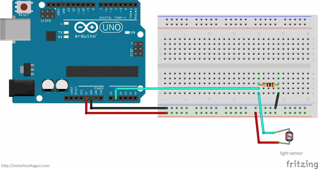
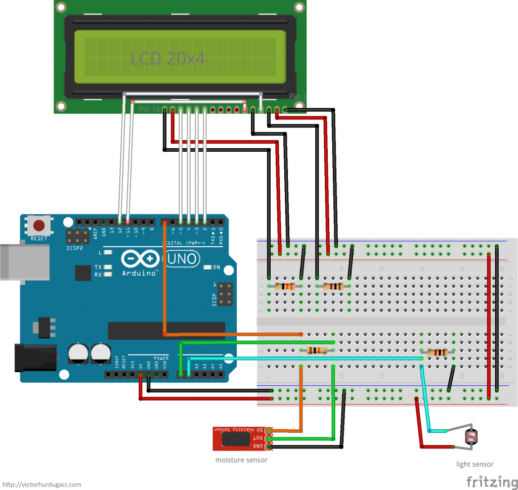
To connect a photoresistor to Arduino you need an extra 1KΩ resistor. One end of the photoresistor is directly connected to 5V (it works with 3.3V too) and the other to a grounded pull-down resistor. The point between the pull-down resistor and the photoresistor is connected to an analog input (A1 in this tutorial) on the board. The voltage read is the amount of light available. You can read a more detailed explanation of how this works, here.
The moisture sensor
Moisture sensors measure the soil’s volumetric water content based on the dielectric constant of the soil. In other words, it measures the soil’s ability to transmit electricity. The more water in the soil, the higher the dielectric constant.
Just like the light sensor, the value read from the sensor is a number. A small number means the soil is dry, while a large number means the soil has water in it.
Some plants don’t like electricity and there is no point in keeping the moisture sensor on all the time. The moisture will not increase/decrease naturally very fast, thus, there is no reason to read the value too often. In the samples, the reading interval is 1 minute but you can safely increase it to 5 or even 10 minutes. Also, power is applied to the sensor only when reading data which is a very short time (20 milliseconds).
There are three pins on the sensor:
- GND (ground) - connected to the ground.
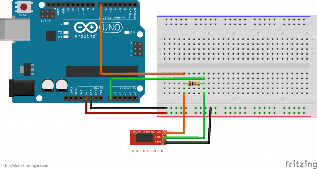
- VCC (power) - instead of connecting this directly to 5V, we are going to use a digital pin. This allows us to turn the sensor on and off.
- SIG (data) - connected to an analog pin on the board. A0 is the pin for this tutorial.
VCC and SIG are connected to a 10KΩ pull-down resistor.
LCD
For this tutorial, I used a 20x4 LCD. If you have a different display, consult the manual to find how to connect it.
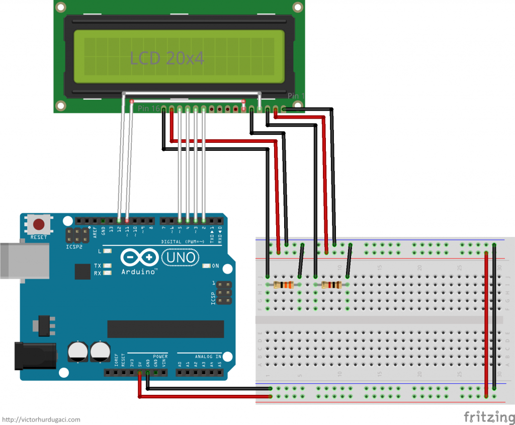
The 16 pins on the 20x4 display are connected as follows:
- Pin 01: ground
- Pin 02: 5V
- Pin 03: (contrast) ground in serial with a 1KΩ resistor. You can use a potentiometer instead.
- Pin 04: Arduino digital pin 11
- Pin 05: ground
- Pin 06: Arduino digital pin 12
- Pin 07: not used
- Pin 08: not used
- Pin 09: not used
- Pin 10: not used
- Pin 11: Arduino digital pin 5
- Pin 12: Arduino digital pin 4
- Pin 13: Arduino digital pin 3
- Pin 14: Arduino digital pin 2
- Pin 15: (backlight) 5V
- Pin 16: (backlight) ground in serial with a 33Ω resistor
You can leave pins 15 and 16 disconnected if you don’t want backlight. If you choose to connect them, don’t run the Arduino on batteries because the LCD draws too much power.
Connecting to Raspberry Pi
The simplest way to connect the Arduino to Raspberry Pi is through a USB cable. This solution is preferred for development and testing because the Arduino board gets power through the same cable. You shouldn’t need an external power source to connect the parts for this tutorial, even with the LCD backlight on.
The alternative is to use the GPIO pins for a serial connection. That is not covered in this tutorial.
Hardware complete
The schematic for the final circuit with the LCD:
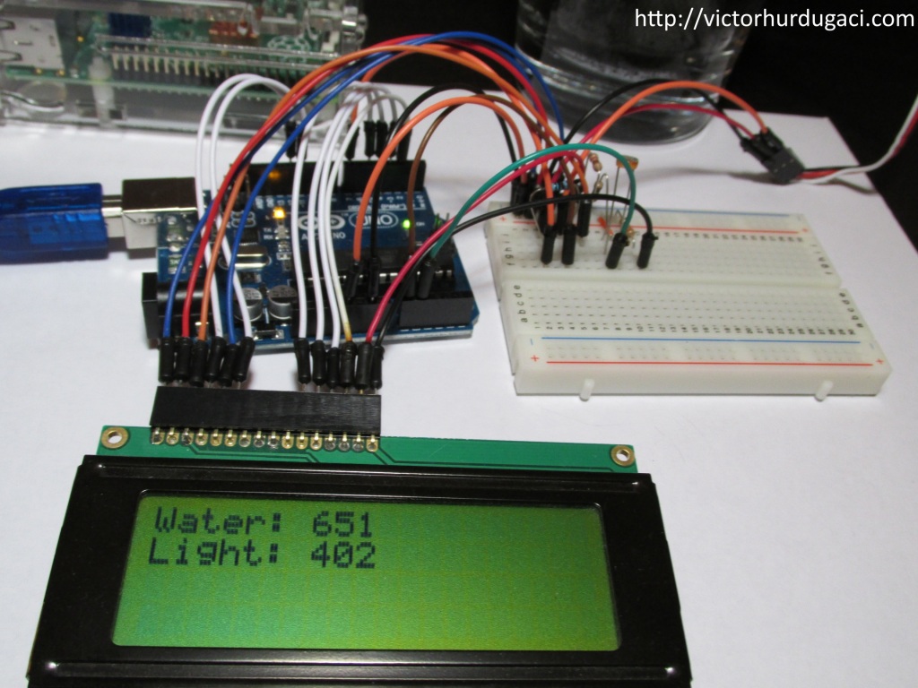
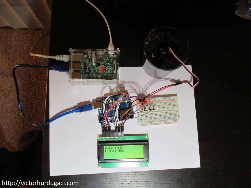
In the end, you should get something like this:
There is a download link for the Fritzing schematics file at the end of this post.
Sending data
Structured data is sent over serial using [SerialProtocol]({% post_url 2014/2014-11-13-serialprotocol-let-the-devices-talk %}). Every minute, a structure containing two 16 bit integers is sent. The two integers represent the values from the two sensors (moisture and light).
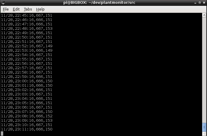
Upon receipt, the program on the Raspberry Pi displays the structure in the console and stores it in a file along with the current date and time. The file is formatted as CSV (Comma Separated Values) with four columns: Date, Time, Moisture, Light.
Different sensors give different values for the same sample and you have to experiment with yours to get the correct reading. To find the intervals for the moisture sensor, put it in dry soil (that will be your dry reference value) and then add water on the soil (that will be the wet reference value). The light sensor can be calibrated by putting it in a dark place and then in front of a sunny window. For my sensors, the intervals are:
| Moisture | Light | |
|---|---|---|
| Low | < 300 | < 200 |
| Normal | 300 - 600 | 200 - 600 |
| High | > 600 | < 600 |
If you are using a Raspberry Pi connected to the Internet and you want it to use the correct local time, follow this tutorial.
Code
The source code for both devices and the schematics are free, open source and available on GitHub{:target=“blank”}.
After the hardware parts are put together, you need some software to make everything work. The Arduino code requires the SerialProtocol library to be installed before compilation; you can follow the instructions here. The same applies to the Raspberry Pi program.
After installing the library, open the Arduino code file in the Arduino IDE and upload it. For the Raspberry Pi, run make (you might have to edit the makefile to point to the correct SerialProtocol library folder) and then run plantmonitor. If you did everything right, you should see the application running and collecting data as shown in the image below:
One interesting aspect of the Arduino program is how the moisture is read. The program will sample the soil and send data once per minute. That is because the moisture will only change slowly. That will help preserve battery (assuming you are running the device on batteries), reduce sensor corrosion and will avoid putting too much electricity in the soil (some plants don’t like it). When moisture is read, the sensor will get power for 20 milliseconds. Because the power pin of the moisture sensor is connected to a digital pin on Arduino, the sensor can be turned on and off by setting the pin high and low, respectively.
void loop()
{
   // Read moisture
   digitalWrite(MOISTURE_PIN_ON_D, HIGH);
   delay(20);
   sensorData.moisture = analogRead(MOISTURE_PIN_A);
   digitalWrite(MOISTURE_PIN_ON_D, LOW);
}
Testing
Once you have put together the parts, compiled the code and uploaded the binaries, it is time for the moment you’ve been waiting for: will it work?
The moisture sensor has two probes; bury them in soil making sure only the probes are buried and not other components on the sensor, and put the light sensor around the same area. Power on the device and you should see the values on the LCD and in the console on Raspberry Pi. The values might change slightly (see the values in the console picture above) after each reading but you should not see big changes unless you change the lighting or moisture.
Resources
Each part links to a website that has the best deal I found. Prices might change after this article is published.
- Arduino Uno
- Raspberry Pi. You might even consider a case for it
- I recommend getting an assortment of resistors
- Wires
- Photoresistor
- Moisture sensor
- 20x4 LCD
If you don’t have any of these parts, instead of buying them separately, I recommend this Arduino Kit (doesn’t include the LCD or the moisture sensor). I bought it myself and I am very satisfied with it.
Source code and schematics file are available on GitHub.
